


 176 / 334

BRAKE PARTS
176
tires &
wheels
axles, hubs
& springs
tongue
accessories
hitches
electrical
brake
parts
trailer
hardware
locks &
pins
towing &
loading
tie downs
tools
chemicals
TRAILER
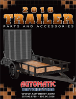
DRUM HUBS
• Hubs are designed to work with hydraulic or electric drum brakes
• Painted brake drum hubs for greater corrosion resistance
• Drum hub only with cups and studs
PART #
HUB CIRCLE
LR81004
82.21
G 5 Stud
10"
LR81003
93.41
G 6 Stud
12"
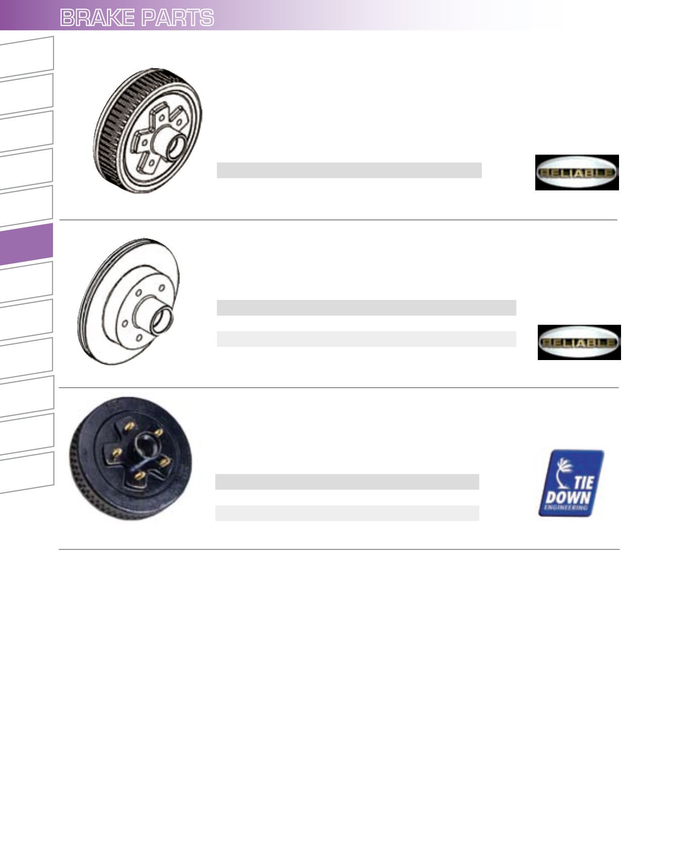
BRAKE DRUM
• 5 stud on 4-1/2"
• E-coated
• Use with hub HSH545
• Recommended for use with 13", 14", and 15" wheels
• 10" drum diameter
• Inner bearing LM68149 (1-3/8"), outer bearing LM44649 (1-1/16")
DISC BRAKE ROTOR
• 5 stud on 4-1/2"
• E-coated
PART #
DESCRIPTION
RL91001
67.90
E Brake Rotor
RL91100
129.45
G L.H. Disc Brake Caliper Assembly
RL91102
129.45
G R.H. Disc Brake Caliper Assembly
PART #
DESCRIPTION
RL51009
71.35
E Brake Drum
BRAKE COMPONENT PARTS
TRAILER BRAKE ADJUSTMENT**
Brakes should be adjusted after the first 200 miles of operation when the brake shoes and drums have “seated” and at 3000 mile intervals, or
as use and performance requires. The brakes should be adjusted in the following manner:
1. Jack up trailer and secure on adequate capacity jack stands. Follow trailer manufacturers recommendations for lifting and supporting the
unit. Check that the wheel and drum rotate freely.
WARNING:
Do not lift or support trailer on any part of the axle or the suspension system.
2. Remove the adjusting hole cover from the adjusting slot on the bottom of the brake backing plate.
3. With a screwdriver or standard adjusting tool, rotate the starwheel of the adjuster assembly to expand the brake shoes. Adjust the brake
shoes out until the pressure of the linings against the drum makes the wheel very difficult to turn.
Note:
With drop spindle axles, a modified adjusting tool with about an 80 degree angle should be used.
4. Then rotate the starwheel in the opposite direction until the wheel turns freely with a slight lining drag.
5. Replace the adjusting hole cover and lower the wheel to the ground.
6. Repeat the above procedure on all brakes.
WARNING:
Never crawl under your trailer unless it is resting on properly placed jack stands.
Follow the trailer manufacturers recommendations for lifting and supporting the unit. Do not lift or place supports on any part of the
suspension system.
**Note:
Trailer Brake Adjustment procedures courtesy Dexter Axle.